Authors: Stephan Laiminger, Michael Url, Martin Schneider, Klaus Payrhuber, INNIO Jenbacher. Copyright: adapted from CIMAC paper
Abstract

Gas engines are providing a wide range of fuel flexibility from burning natural gas and a variety of non- natural gaseous fuels from low British Thermal Unit (BTU) gases as well as gases containing a high hydrogen content. Hydrogen containing gases can be found as by-product from steel (furnace gas) or chemical process, or alternatively hydrogen is produced and blended to natural gas.
In the mid-sized power generation segment, Jenbacher gas engines are a proven technology provider to utilise high hydrogen gaseous fuels. Coke oven gases as well as byproduct gases from chemical processes containing a hydrogen content up to 70 volumes % have been used in various types of engines and accumulated well more than one million operating hours. Hydrogen from renewable sources like wood gasification (in syngas) can contain up to 50 volume % of hydrogen. Hydrogen from electrolysis is typically provided as a 100 volume % and purified H2 fuel and considered as carbon free (green H2) when electricity is produced from renewable sources.
One of the main purposes to produce green hydrogen is to add it to the natural gas system, because the natural gas system is seen as a seasonal and large energy storage and necessary for balancing the intermittent electricity production from renewables wind and solar. When hydrogen is mixed with natural gas, the hydrogen content can vary in a wide range. Gas engines have the capability to burn gases with a wide range of hydrogen content, but there are also some challenges with a potentially high fluctuation of the hydrogen content or fast rate of change. The future advantages, the challenges as well as the experience with high hydrogen gases on Jenbacher gas engines will be discussed in this paper.
Introduction
The world and its climate are changing faster than ever before. With CO2 in the atmosphere already passing the 400ppm mark, CO2 pollution must be lowered to limit rising atmospheric temperatures driven by global warming. Although there are a variety of scenarios regarding rising greenhouse gas (GHG) and the climate’s future, all show that we must move away from fossil fuels and carbon- based energy.
Because energy demand will continue to grow, we need to reduce GHG emissions during energy production as well as losses on the end user side to keep the world’s climate under control. The International Energy Agency (IEA) has created a scenario on required CO2 reduction (Figure 1), with the target to stay in the +2°C temperature increase range by 2100. With our products, INNIO can support such efforts as the move to renewables, fuel switching, and efficiency increases to reach this target.
Increasing the efficiency of our Jenbacher* gas engines is INNIO’s day-to-day business, and high GHG emission reductions can be reached by a combined heat and power (CHP) application. When replacing a coal power plant with a modern CHP gas engine, a reduction in the magnitude of 70% CO2 can be reached. In addition, INNIO engines can be operated with different fuels and also from non-fossil sources. Basically, all burnable gases can be converted using gas engines.
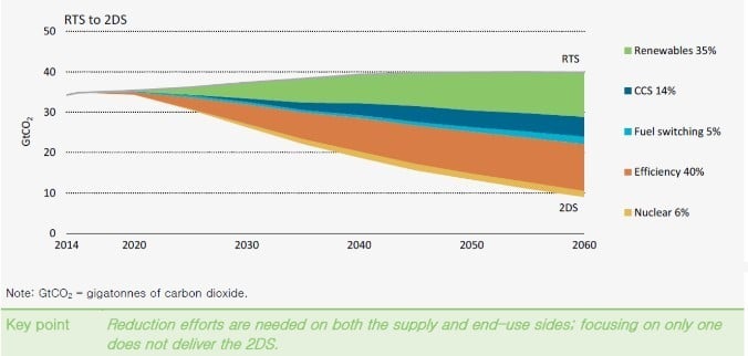
Figure 1: GtCO2 reduction effort needed until 2060 [7]
Reduction capabilities are counterbalanced by the strong GHG potential of methane, meaning methane slip must be kept as low as possible. Driven by fuel properties, switching to natural gas directly lowers CO2 emissions by 25% compared to diesel engines. Replacing an old coal plant with a modern CHP gas engine plant can lead to a CO2 reduction of up to 70%. With gas engines well suited to convert “waste gases” or biogases to heat and power, 100% CO2 reduction can be achieved. A change from diesel to gas, to waste gas utilisation, or for an efficiency increase is a step in the right direction.
Due to the volatility of renewables, we will face the challenge of energy storage. If electric energy is stored as H2, gas engines will be forced to use gases with a high H2 content. INNIO products are prepared to take on this challenge.
Decarbonisation
Stepping away from fossil fuels, also called decarbonisation, is a burning topic all over the world. Since traffic is a main contributor to CO2 emissions, electromobility is being widely considered and studied. Recently, many studies have shown possible routes to 100% decarbonisation. One study, published by FVV, shows three scenarios that could make this happen. The scenarios are shown in Figure 2. Electric energy can be provided to the vehicle from a battery or from hydrogen converted in a fuel cell, or the vehicle can be powered conventionally with E-Fuel. It needs to be mentioned that the study assumes that current state-of-the-art batteries are not an option for trucks. If they run electrically, they also could be powered by overhead wiring.
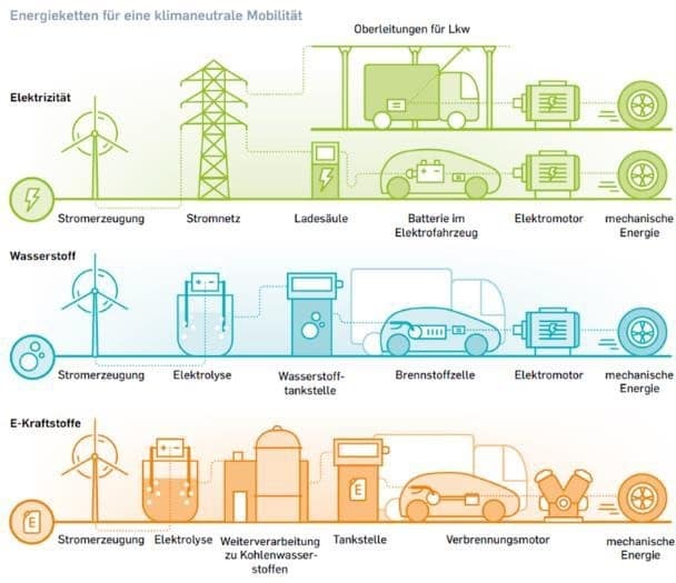
Figure 2: Concepts for E-Fuel in transport [3]
The electric-powered scenario needs instantaneous electric power through recharging or overhead wiring. Hydrogen and a synthetic fuel can be stored for a time when renewable energy (hydro, wind or photovoltaic) is not available. The key for sustained decarbonisation is the possibility of storing electric energy in an efficient and cost- effective way. From the FVV point of view, the solution to decarbonisation will be not a single technology, but a combination of all three. This will require H2 infrastructure, because H2 is the first step in the process of E-Fuels and H2 direct used as vehicle fuel. A very likely scenario is that H2 also will be fed into the natural gas (NG) pipeline to store oversupply before a complete H2 infrastructure is built. The consequence will force customers to operate on a blend of NG and H2.
In all of these concepts, renewables provide electric power, which will need to be available during times of undersupply of wind and solar power. How to store electric energy is the question to be answered.
Energy Storage
Due to the volatility of renewable energy sources such as wind and solar, storage is the key technology to be solved. As power needs to be provided all year round, a high amount of energy needs to be stored for a longer period (seasonal). A comparison of different technologies is shown in Figure 3. For a sustainable move to renewable energy, a seasonal storage of large amounts of energy is needed. Batteries are only good for the storage of a maximum of a day’s demand. Seasonal storage must follow the H2 route, at least as an intermediate product. Even with pumped hydro or compressed air storage, solar energy can’t be harvested in summer and stored for the winter.
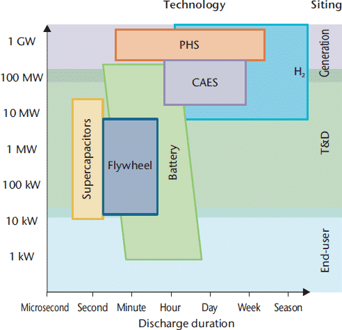
Figure 3: Energy storage options capacity vs. duration [2]
H2 produced via electrolyses of water is the starting point for different storage strategies. H2 can be stored directly, in the underground in caverns, or it can be fed into the natural gas grid leading to a blend of natural gas and H2. Up to 5% H2 currently is allowed, but numbers up to 10% have been proposed for the near future. It is likely that the content of H2 in the natural gas pipeline will increase even more in the future, or else a separate H2 distribution system will need to be installed. At least for a transition period it’s expected that H2 will be distributed via the existing NG grid.
An option to keep the actual gas and diesel infrastructure without changes can be reached by processing H2 to synthetic natural gas (SNG) or liquid E-Fuel. This is the 3rd FVV scenario shown in Figure 2, an easy bridge technology from the transport infrastructure. But there are downsides of this process (Figure 4). Next to the high production costs, the need for CO2 is a challenge. Despite the new record high of CO2 in the atmosphere, the concentration is still very low for an efficient separation process.
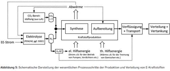
Figure 4: E-Fuel production flow chart [3]
If a cost-effective E-Fuel could be produced, with qualities similar to diesel, gasoline or natural gas, most of the problems to a decarbonised future would be solved because there would be nearly no change required to the end users’ assets. Right now, there are some small- to medium-scale demonstration plants for E-Fuel production in planning and operation. A successful scale up would enable a cost-effective large-scale production and storage of E-Fuel.
Hydrogen As a Fuel
The two technology areas, traffic decarbonisation and long-term energy storage, depend on H2. As H2 will be transported in pipelines, the need for flexible H2-tolerant gas engines will rise.
Since gas engines are already well suited to utilise different gases, it is a viable option to use H2 or H2 and natural gas blends directly. Of course, this is not an off-the-shelf product and certain technologies and optimisations are needed to cope with the changing gas qualities. The CIMAC WG 17 has published a positioning paper on “Impact of Gas Quality on Gas Engine Performance.”
The gas marked liberalisation will have a significant impact on fuel properties. Some parameters are shown in Figures 5, 6 and 7.
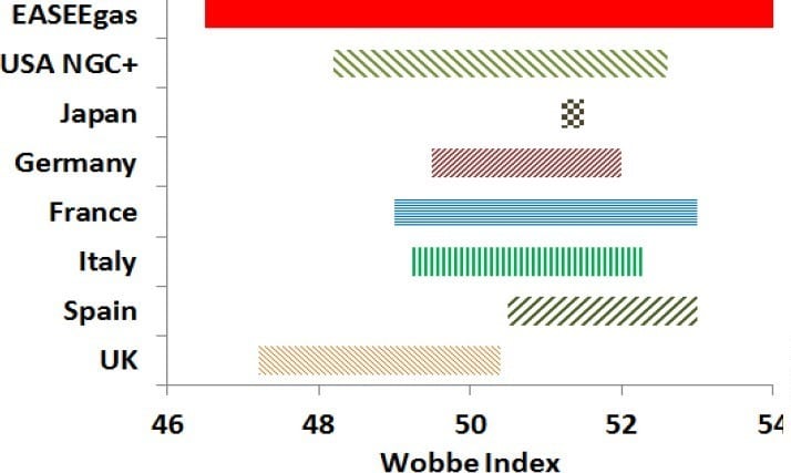
Figure 5: Actual values for Ws and rules in different countries [1]
The proposed values of the Wobbe Index (Ws) are different from country to country. And a general liberalisation of gas quality is expected. It’s not implied that every customer will experience this range; locally, the gas quality could be relatively constant.
The Wobbe Index is not the most critical value for gas engines. As gas engines are typically operated as Otto-SI engines, with the risk of knocking, the Methane Number is more important. The methane number does not correlate with the Wobbe Index (Figure 6), but it can be seen that a gas with a Wobbe Index of 54 has a methane number of less than 65, which is unacceptable for most high-efficiency gas engines.
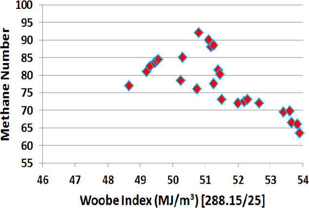
Figure 6: Methane Number vs. Wobbe Index [1]
New engines can be designed to operate on a wide band of gas qualities with a penalty on efficiency and other performance parameters. The real challenge is the existing fleet. Gas engines are designed to be in use for several years, so a quick change in gas qualities will force the development of upgrade kits, because just stopping the engines is not an option.
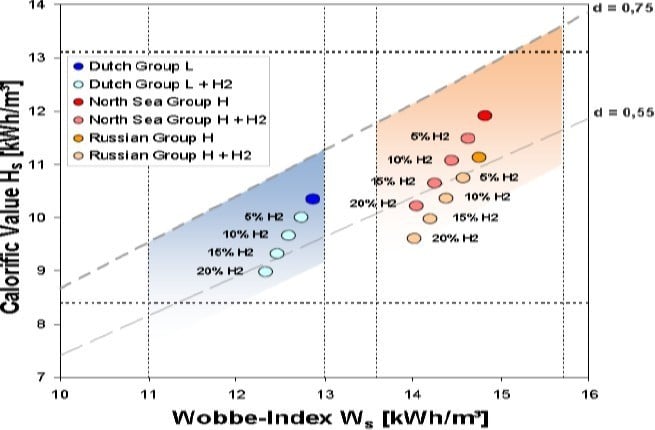
Figure 7: Impact of hydrogen on HV, Ws and density [1]
The higher hydrocarbons (C4 and C4+) sometimes found in LNG fuel will lower the methane number, and the admixture of hydrogen has a comparable effect. A 10% limit for hydrogen is under discussion from the gas industry while manufacturers of gas turbines and engines have specified limits between 1% and 5%. Even with 10% admixture, the resulting density of the mixed gas will be for some base gases out of the current specification for density ratio (0.55<d<0.75), as shown in Figure 7. The admixture of bio-methane can bring additional impurities such as siloxanes and sulphur to the gas network, which would negatively impact consumers but would have especially profound effects on gas engines.
With H2 potentially the key technology for decarbonisation, a transformation to frequent changes in gas quality will happen. A scenario is storage of H2 in the existing natural gas pipeline infrastructure (Figure 8). Hydrogen will be produced in large-scale plants and distributed to end consumers or will be processed further to synthetic fuels.
Gas engines need to be able to be operated with gases, in the best case, from 0 to 100% H2 content.
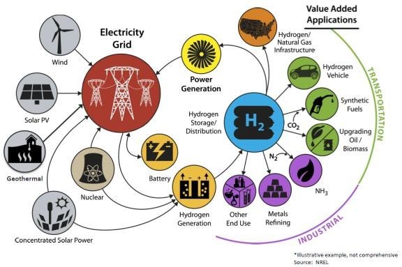
Figure 8: Hydrogen production and utilisation [4]
Hydrogen Combustion Strategy
Jenbacher gas engines from INNIO have much experience in utilising all kinds of non-natural gases. Some of these gases, such as landfill and coalmine gas, are based on CH4 and have combustion behavior that is similar to natural gas. The other large group is based on H2 and CO, like gasification and steel production gases. The H2 content can be as high as 70% in these applications, and various types of INNIO’s Jenbacher gas engines already have reached more than 1 million operating hours. The gas quality remains stable in normal operation, so engines can be designed to use these gases. If a large variation on gas quality is expected, more effort is needed, and from the engine performance compromises need to be accepted.
Figure 9 shows some examples of Jenbacher gas engine projects from industry waste gas usage. With this broad range of experience, INNIO is on track to reach the target of a fully flexible engine able to use fuels from 0 to 100% H2.
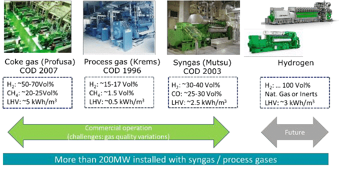
Figure 9: Different gas qualities with H2 content
The INNIO gas engine versions for non-natural gas applications are different from standard natural gas engines. One example is the piston design from a Jenbacher Type 6 gas engine (Figure 9). The standard design is a flat top or very shallow bowl design, turbulence driven by the gas-fueled pre- chamber. Gas with a high H2 content cannot be converted safely with a pre-chamber combustion system.

Figure 10: Example of piston bowl shapes
A direct ignition system is the preferred route with a defined turbulence level in the main chamber driven by an intake swirl and a specially shaped piston to break the swirl.
The main driver for a stable H2 combustion is the combustion strategy, started from the mixture preparation, charge motion, ignition of the charge to the main combustion process itself, and the charging strategy.
A combustion chamber designed for fuels with a high amount of H2 is different than a chamber for 100% natural gas fuels. A single cylinder engine (SCE) with different H2 content was performed and shown in Figures 11 and 12. An increase in H2 content is accelerating the combustion and leads to a very efficient combustion process.
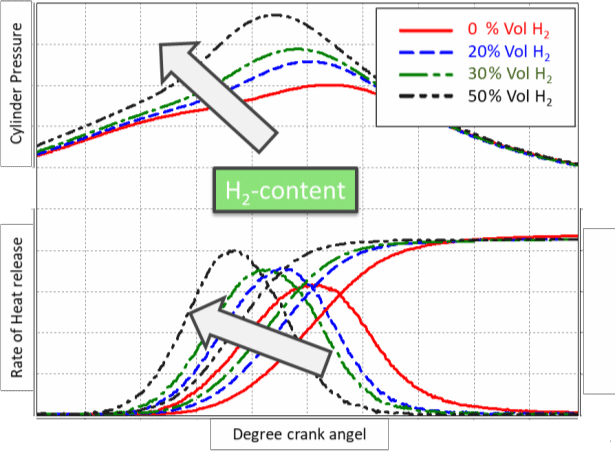
Figure 11: Rate of heat release with different H2 content
It needs to be mentioned again that the combustion chamber was changed from the original design to handle the fuel with H2 content. The power was kept constant at this experiment, and this leads to an increased ‘peak firing pressure’ of the engine. The base structure must be able to handle this or the power output must be reduced.
The influence on the overall engine is shown in Figure 12. The key performance parameters are calculated based on the SCE results. The very fast combustion with 50% H2 content cannot be transferred one-to-one for very good overall engine efficiency. Keeping the NOx emissions at the same level makes it necessary to lean out the charge mixture. This leads to a higher boost pressure demand and finally to increased pumping losses.
The advantage of the fast combustion is overcompensated by the increased losses. For higher H2 content, another change of the combustion chamber design is needed. But as was demonstrated, the small amount of H2 in the fuel gas creates efficiency gains and enables a stable engine operation with lower NOx emissions.

Figure 12: Engine performance with different H2 content
But especially with gases with high H2 and/or CO content, we have observed abnormal combustion phenomena. Cycles start to accelerate the combustion and switch to self ignition without knocking. In Figure 13, an in-cylinder pressure trace is shown of different combustion cycles. In addition, the ignition voltage signal is plotted (green line), and it’s clearly visible that the combustion of the ‘red cycle’ starts with an early, self-ignited combustion. This early combustion is fast enough that all the charge is converted and no knocking occurs, and this leads to a very high peak firing pressure. The downside is that, because there is no knocking, the standard engine control cannot see these phenomena. This can cause heavy engine damage. With an in-cylinder pressure- based control system, these phenomena can be seen, and safe and stable engine operation is possible. At INNIO, this has been in operation on many of our non-natural gas versions for years.
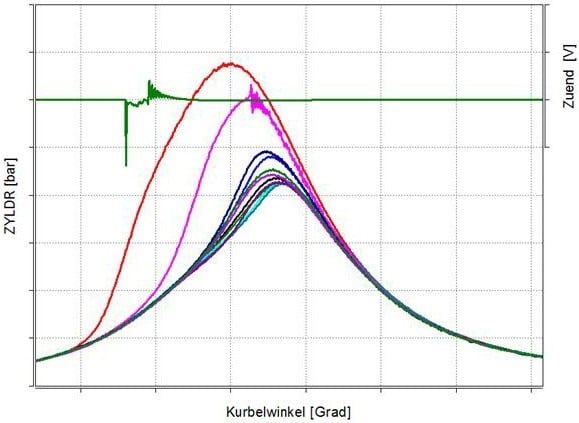
Figure 13: Abnormal combustion phenomena
Another option to avoid these abnormal combustion phenomena is to change to a combustion concept with direct H2 injection in the main combustion chamber. There is also an option to ignite conventionally with a spark plug or, as shown in Figure 14, with a small amount of diesel.
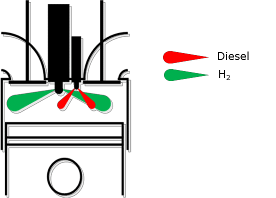
Figure 14: Alternative hydrogen combustion process [5]
This concept with H2 direct injection and alternatively ignition with a diesel pilot injection is a research project performed from the Large Engines Competence Center GmbH (LEC). It is a part of the European Union’s Horizon 2020 research and innovation program under grant agreement No. 768945.
Of course, there will be other options to utilise H2 in a gas engine. Some first concepts have been realised, and there are more to come.
Examples & Development
INNIO has many plants operating with gases that have H2 content. In Figure 15, a P2G demonstration plant in Argentina is shown. Renewable energy from a wind park is stored as H2, and in times of high demand H2 is converted in a gas engine back to electricity. The engine is not designed for 100% H2 content, base fuel is NG and up to 40% H2 is admixed with just a slight derating in power. This plant has been in operation for about 10 years and is still running.
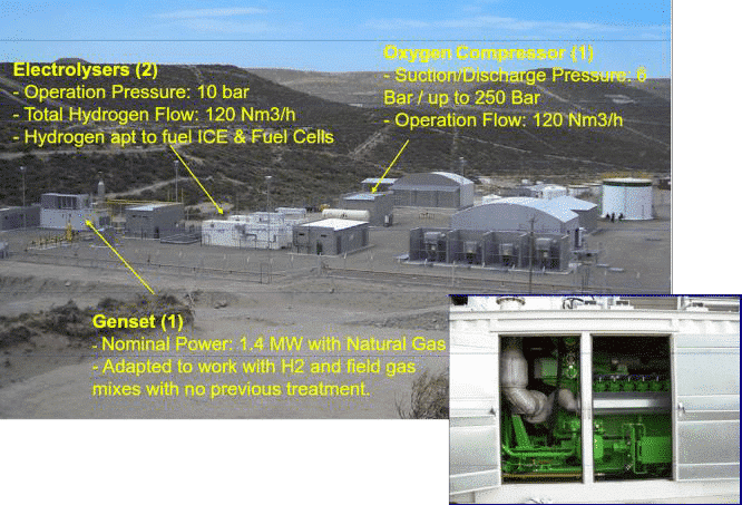
Figure 15: P2G demonstration plant in Argentina
For a future application, an advanced concept is the already mentioned European Union’s Horizon 2020 research and innovation program HyMethShip. Energy storage is realised via methanol (CH3OH) out of H2 from renewable energy sources and a closed CO2 cycle. A high- level flow chart is shown in Figure 16.
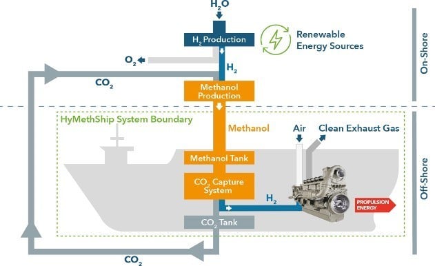
Figure 16: “Emission-free” ship propulsion [5]
The challenge in methanol production is to also get CO2 from renewable sources. In this concept, CO2 is captured on the ship and brought back to the methanol plant, closing the challenging CO2 loop.
A more detailed process map of the ship infrastructure is shown in Figure 17. A cornerstone of the concept is a gas engine to be operated with H2 as fuel, or any blend of H2 and methanol. The project is a technology demonstration project, and if it’s successful in a marine application it also could work as an energy storage unit in power generation.
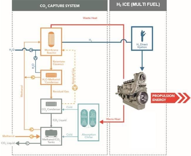
Figure 17: “Emission-free” ship propulsion [5]
The main process steps are:
- The energy is stored in a methanol tank on the ship.
- Methanol is reformed on the ship to H2 and CO2.
- H2 and CO2 are separated via an integrated membrane-reformer.
- CO2 is condensed and stored as a liquid and brought back to the methanol plant.
- H2 is converted in a gas engine to propulsion energy, while producing very low emissions.
The project HyMethShip will demonstrate the readiness and functionality of this concept shown in lab scale, with performance evaluation still outstanding. A detailed project paper presentation from LEC also is available (CIMAC paper 104).
Conclusion
To reach the goal of 100% decarbonisation, storage of renewable energy for longer than a day is needed. For seasonal storage in particular, it is beneficial to choose chemical energy storage. Hydrogen and/or SNG can be fed into the existing natural gas infrastructure of pipelines and cavern storage. When renewable energy production is lacking, the H2-NG mixtures then can be flexibly converted into power and heat via a gas engine. Therefore, a fully flexible engine needs to be developed, capable of using blends from 0 to 100% H2. At INNIO, we have technologies to demonstrate these requirements for new units. A question is how to deal with the existing fleet.
Definitions, Acronyms, Abbreviations
CAES: compresses air energy storage
CCS: Carbon Capture Storage
CHP: Combined Heat and Power
GHG: Green House Gas
IEA: International Energy Agency
NG: Natural Gas
NNG: Non-Natural Gas
P2G: Power to Gas
P2G: Power to Gas
PFP: Peak Firing Pressure
SCE: Single Cylinder Engine
SNG: Synthetic Natural Gas
* Jenbacher is a trademark.
Acknowledgements
Special thanks to colleagues from the LEC GmbH, INNIO’s development partner in combustion development projects. LEC GmbH is also the project coordinator in the HyMethShip program, the European Union’s Horizon 2020 research and innovation program under grant agreement No. 768945.
References and Bibliography
CIMAC Positioning Paper 07/2015 Impact of Gas Quality on Gas Engine Performance
IEA ”Roadmap – Hydrogen and Fuel Cells“
FVV- Optionen für eine klimaneutrale Mobilität im Jahr 2050; Energiepfade für den Straßenverkehr der Zukunft
NREL; National Renewable Energy Laboratory
European Union’s Horizon 2020 research and innovation program under grant agreement No. 768945.
IEA “Tracking Clean Energy Progress 2017”


